Rubber components under multiaxial cyclic loading conditions are often considered to have failed or degraded when there is a change is the stiffness of the component and it is no longer able to provide the performance it is designed for. Elastomeric polymer components are widely used in many industries like automotive, aerospace and biomedical applications due to their good vibration isolation and energy absorption characteristics. The type of loading normally encountered by these components in service is mutiaxial in nature. Fatigue failure is thus a major consideration in their design and availability of testing techniques to predict fatigue life under these complex conditions is a necessity.
In real world applications all materials and products are subjected to a wide variety of vibrating or oscillating forces. Fatigue testing consists of applying a cyclic load to a test specimen or the component to determine in-service performance during situations similar to real world working conditions.
Advanced Scientific and Engineering Services (AdvanSES) specializes in Fatigue Testing of Automotive Components including hoses, engine mounts, vibration isolators, silent bushes etc. Fatigue testing can be carried out in stress & force control, strain control or displacement control. The deformation modes under which fatigue tests are generally carried out are tension – tension, compression – compression, tension – compression and compression – tension.
ASTM D 5992 Test Standard applies to Dynamic Properties of Rubber Vibration Products such as springs, dampers, and flexible load-carrying devices, flexible power transmission couplings, vibration isolation components and mechanical rubber goods. The standard applies to to the measurement of stiffness, damping, and measurement of dynamic modulus.
Dynamic testing is performed on a variety of rubber parts and components like engine mounts, hoses, conveyor belts, vibration isolators, laminated and non-laminated bearing pads, silent bushes etc. to determine their response to dynamic loads and cyclic loading.
Personalized consultation from AdvanSES engineers can streamline testing and provide the necessary tools and techniques to accurately evaluate material performance under field service conditions.
The quantities of interest for measurements are tan delta, loss modulus, storage modulus, phase etc. All of these properties are viscoleastic properties and require instruments, techniques and measurement practices of the highest quality.
ASTM D5992 covers the methods and process available for determining the dynamic prop- erties of vulcanized natural rubber and synthetic rubber compounds and components. The standard covers the sample shape and size requirements, the test methods, and the pro- cedures to generate the test results data and carry out further subsequent analysis. The methods described are primarily useful over the range of temperatures from cryogenic to 200◦C and for frequencies from 0.01 to 100 Hz, as not all instruments and methods will accommodate the entire ranges possible for material behavior.
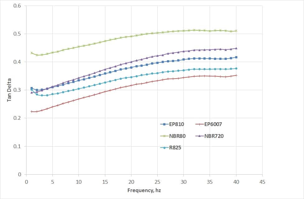
Figures(.43and.44) show the results from a frequency sweep test on five (5) different elastomer compounds. Results of Storage modulus and Tan delta are plotted.
Figure .43: Plot of Storage Modulus Vs Frequency from a Frequency Sweep Test
The frequency sweep tests have been carried out by applying a pre-compression of 10 % and subsequently a displacement amplitude of 1 % has been applied in the positive and negative directions. Apart from tests on cylindrical and square block samples ASTM D5992 recommends the dual lap shear test specimen in rectangular, square and cylindri- cal shape specimens. Figure (.45) shows the double lap shear shapes recommended in the standard.
Figure .44: Plot of Tan delta Vs Frequency from a Frequency Sweep Test
Polymeric rubber components are widely used in automotive, aerospace and biomedical systems in the form of vibration isolators, suspension components, seals, o-rings, gaskets etc. Finite element analysis (FEA) is a common tool used in the design and development of these components and hyperelastic material models are used to describe these polymer materials in the FEA methodology. The quality of the CAE carried out is directly related to the input material property and simulation technology. Nonlinear materials like polymers present a challenge to successfully obtain the required input data and generate the material models for FEA. In this brief article we review the limitations of the hyperleastic material models used in the analysis of polymeric materials.
Theory:
A material model describing the polymer as isotropic and hyperelastic is generally used and a strain energy density function (W) is used to describe the material behavior. The strain energy density functions are mainly derived using statistical mechanics, and continuum mechanics involving invariant and stretch based approaches.
Statistical Mechanics Approach
The statistical mechanics approach is based on the assumption that the elastomeric material is made up of randomly oriented molecular chains. The total end to end length of a chain (r) is given by
Where µ and lm are material constants obtained from the curve-fitting procedure and Jelis the elastic volume ratio.
Invariant Based Continuum Mechanics Approach
The Invariant based continuum mechanics approach is based on the assumption that for a isotropic, hyperelastic material the strain energy density function can be defined in terms of the Invariants. The three different strain invariants can be defined as
I1 = l12+l22+l32
I2 = l12l22+l22l32+l12l32
I3 = l12l22l32
With the assumption of material incompressibility, I3=1, the strain energy function is dependent on I1 and I2 only. The Mooney-Rivlin form can be derived from Equation 3 above as
With C01 = 0 the above equation reduces to the Neo-Hookean form.
Stretch Based Continuum Mechanics Approach
The Stretch based continuum mechanics approach is based on the assumption that the strain energy potential can be expressed as a function of the principal stretches rather than the invariants. The Stretch based Ogden form of the strain energy function is defined as
where µiand αi are material parameters and for an incompressible material Di=0.
Neo-Hookean and Mooney-Rivlin models described above are hyperelastic material models where, the strain energy density function is calculated from the invariants of the left Cauchy-Green deformation tensor, while in the Ogden material model the strain energy density function is calculated from the principal deformation stretch ratios.
The Neo-Hookean model, one of the earliest material model is based on the statistical thermodynamics approach of cross-linked polymer chains and as can be studied is a first order material model. The first order nature of the material model makes it a lower order predictor of high strain values. It is thus generally accepted that Neo-Hookean material model is not able to accurately predict the deformation characteristics at large strains.
The material constants of Mooney-Rivlin material model are directly related to the shear modulus ‘G’ of a polymer and can be expressed as follows:
G = 2(C10+ C01) …………………………….…(6)
Mooney-Rivlin model defined in equation (4) is a 2nd order material model, that makes it a better deformation predictor that the Neo-Hookean material model. The limitations of the Mooney-Rivlin material model makes it usable upto strain levels of about 100-150%.
Ogden model with N=1,2, and 3 constants is the most widely used model for the analysis of suspension components, engine mounts and even in some tire applications. Being of a different formulation that the Neo-Hookean and Mooney-Rivlin models, the Ogden model is also a higher level material models and makes it suitable for strains of upto 400 %. With the third order constants the use of Ogden model make it highly usable for curve-fitting with the full range of the tensile curve with the typical ‘S’ upturn.
Discussion and Conclusions:
The choice of the material model depends heavily on the material and the stretch ratios (strains) to which it will be subjected during its service life. As a rule-of-thumb for small strains of approximately 100 % or l=2.0, simple models such as Mooney-Rivlin are sufficient but for higher strains a higher order material model as the Ogden model may be required to successfully simulate the ”upturn” or strengthening that can occur in some materials at higher strains.
REFERENCES:
ABAQUS Inc., ABAQUS: Theory and Reference Manuals, ABAQUS Inc., RI, 02
Attard, M.M., Finite Strain: Isotropic Hyperelasticity, International Journal of Solids and Structures, 2003
Bathe, K. J., Finite Element Procedures Prentice-Hall, NJ, 96
Bergstrom, J. S., and Boyce, M. C., Mechanical Behavior of Particle Filled Elastomers,Rubber Chemistry and Technology, Vol. 72, 2000
Beatty, M.F., Topics in Finite Elasticity: Hyperelasticity of Rubber, Elastomers and Biological Tissues with Examples, Applied Mechanics Review, Vol. 40, No. 12, 1987
Bischoff, J. E., Arruda, E. M., and Grosh, K., A New Constitutive Model for the Compressibility of Elastomers at Finite Deformations, Rubber Chemistry and Technology,Vol. 74, 2001
Blatz, P. J., Application of Finite Elasticity Theory to the Behavior of Rubber like Materials, Transactions of the Society of Rheology, Vol. 6, 196
Kim, B., et al., A Comparison Among Neo-Hookean Model, Mooney-Rivlin Model, and Ogden Model for Chloroprene Rubber, International Journal of Precision Engineering & Manufacturing, Vol. 13.
Boyce, M. C., and Arruda, E. M., Constitutive Models of Rubber Elasticity: A Review, Rubber Chemistry and Technology, Vol. 73, 2000.
Srinivas, K., Material Characterization and FEA of a Novel Compression Stress Relaxation Method to Evaluate Materials for Sealing Applications, 28th Annual Dayton-Cincinnati Aerospace Science Symposium, March 2003.
Srinivas, K., Material Characterization and Finite Element Analysis (FEA) of High Performance Tires, Internation Rubber Conference at the India Rubber Expo, 2005.
The application of computational mechanics analysis techniques to elastomers presents
unique challenges in modeling the following characteristics:
1) The load-deflection behavior of an elastomer is markedly non-linear.
2) The recoverable strains can be as high 400 % making it imperative to use the large
deflection theory.
3) The stress-strain characteristics are highly dependent on temperature and rate effects
are pronounced.
4) Elastomers are nearly incompressible.
5) Viscoelastic effects are significant.
The inability to apply a failure theory as applicable to metals increases the complexities regarding the failure and life prediction of an elastomer part. The advanced material models available today define the material as
hyperelastic and fully isotropic. The strain energy density (W) function is used to describe the material behavior.
To help you better understand, we broke down everything you need to know about materials, testing, FEA verifications and validations etc.
2. Computational Mechanics in the design and development of polymeric components
3. Why there are recommended testing protocols
4. Curve-fitting the Material Constants.
5. Verifications and Validations of FEA Solutions
Let’s talk Engineering with Rubber.
Our expert engineers can help you get your next product into the market in the shortest possible team or solve your durability and fatigue problems. To learn more, fill up the contact form and get in touch
Abaqus – Tips and Tricks: When to use what Elements?
For a 3D stress analysis, ABAQUS offers different typess of linear and quadratic hexahedral elements, a brief description is as below;
Linear Hexahedral: C3D8 further subdivided as C3D8R, C3D8I, and C3D8H
Quadratic Hexahedral: C3D20 further subdivided as C3D20R, C3D20I, and C3D20H, C3D20RH
Linear Tetrahedral: C3D4 further subdivided as C3D4R, and C3D4H
Quadratic Tetrahedral: C3D10 further subdivided as C3D10M, C3D10I and C3D10MH
Prisms: C3D6 further subdivided as C3D6R, and C3D6H
In three-dimensional (3D) finite element analysis, two types of element shapes are commonly utilized for mesh generation: tetrahedral and hexahedral. While tetrahedral meshing is highly automated, and relatively does a good job at predicting stresses with sufficient mesh refinement, hexahedral meshing commonly requires user intervention and is effort intensive in terms of partitioning. Hexahedral elements are generally preferred over tetrahedral elements because of their superior performance in terms of convergence rate and accuracy of the solution.
The preference for hexahedral elements(linear and uadratic) can be attributed to the fact that linear tetrahedrals originating from triangular elements have stiff formulations and exhibit the phenomena of volumetric and shear locking. Hexahedral elements on the other hand have consistently predicted reasonable foce vs loading (stiffness) conditions, material incompressibility in friction and frictionless contacts. This has led to modeling situations where tetrahedrals and prisms are recommended when there are frictionless contact conditions and when the material incompressibility conditiona can be relaxed to a reasonable degree of assumption.
A general rule of thumb is if the model is relatively simple and you want the most accurate solution in the minimum amount of time then the linear hexahedrals will never disappoint.
Modified second-order tetrahedral elements (C3D10, C3D10M, C3D10MH) all mitigate the problems associated with linear tetrahedral elements. These element offer good convergence rate with a minimum of shear or volumetric locking. Generally, observing the deformed shape will show of shear or volumetric locking and mesh can be modified or refined to remove these effects.
C3D10MH can also be used to model incompressible rubber materials in the hybrid formulation. These variety of elements offer better distribution of surface stresses and the deformed shape and pattern is much better. These elements are robust during finite deformation and uniform contact pressure formulation allows these elements to model contact accurately.
The following are the recommendations from the house of Abaqus(1);
Minimize mesh distortion as much as possible.
A minimum of four quadratic elements per 90o should be used around a circular hole.
A minimum of four elements should be used through the thickness of a structure if first-order, reduced-integration solid elements are used to model bending.
Abaqus Theory and Reference Manuals, Dassault Systemes, RI, USA
Finite element analysis is widely used in the design and analysis of elastomer components in the automotive and aerospace industry. Numerous publications [7-11] addressed the applications of FEA and have established the method as a reliable tool to predict stress analysis parameters under different loading conditions. In this report we have studied the different material models available to simulate elastomer behavior. Nonlinear Finite element code Abaqus® was used to develop the 2D Axisymmetric and 3D models. Generalized continuum axisymmetric and hexahedral elements were used to model the structures in two and three dimensions using these hyperelastic material models. Testing of materials to characterize the rubber compounds has been carried out in-house and the material constants have been developed using the regression analysis based curve-fitting procedure.
MATERIAL TESTING AND CHARACTERIZATION PROCEDURE:
The application of computational mechanics analysis techniques to elastomers presents unique challenges in modeling the following characteristics:
The load-deflection behavior of an elastomer is markedly non-linear.
The recoverable strains can be as high 400 % making it imperative to use the large deflection theory.
The stress-strain characteristics are highly dependent on temperature and rate effects.
Elastomers are nearly incompressible.
Viscoelastic effects are significant.
Finite element codes like Abaqus® Ansys®, LS-Dyna® and MSC-Marc® generally require the input of test data covering the maximum range, which the elastomer product experiences in service conditions. Test data from the main principal deformation modes are generally used as shown in Figure 1. When designing a product from scratch all the four tests can be used to generate the constants for the design but for failure analysis one may not have enough material to carry out all the tests.
Figure 1: AdvanSES Material Characterization Tests
STRAIN ENERGY FUNCTIONS:
In the FE analysis of elastomeric materials, the material is characterized by using different forms of the strain energy density function. The strain energy density of a solid can be defined as the work done per unit volume to deform a material from a stress free reference or original state to a final state. The strain energy density functions have been derived using a Statistical mechanics, and Continuum mechanics involving Invariant and Stretch based approaches.
Statistical Mechanics Approach
The statistical mechanics approach is based on the assumption that the elastomeric material is made up of randomly oriented molecular chains. The total end to end length of a chain (r) is given by
Where µ and lm are material constants obtained from the curve-fitting procedure and Jelis the elastic volume ratio.
· Invariant Based Continuum Mechanics Approach
The Invariant based continuum mechanics approach is based on the assumption that for a isotropic, hyperelastic material the strain energy density function can be defined in terms of the Invariants. The three different strain invariants can be defined as
I1 = l12+l22+l32
I2 = l12l22+l22l32+l12l32
I3 = l12l22l32
With C01 = 0 the above equation reduces to the Neo-Hookean form.
Stretch Based Continuum Mechanics Approach
The Stretch based continuum mechanics approach is based on the assumption that the strain energy potential can be expressed as a function of the principal stretches rather than the invariants. The Stretch based Ogden form of the strain energy function is defined as
where µi and ai are material parameters and for an incompressible material Di=0.
The choice of the material model depends heavily on the material and the stretch ratios (strains) to which it will be subjected during its service life. As a rule-of-thumb for small strains of approximately 100 % or lb2, simple models such as Mooney-Rivlin are sufficient but for higher strains a higher order material model as the Ogden model may be required to successfully simulate the ”upturn” or strengthening that can occur in some materials at higher strains.
Figure 2 shows the verification procedure that can be carried out to verify the FEA Model as well as the used material model. The procedure also validates the boundary conditions if the main deformation mode is simulated on an material testing system (MTS) and results verified computationally. Figure 2 shows a bushing on a testing jig, and the plot show the FEA model and load vs. displacement results compared to the experimental results. It is generally observed that verification procedures work very well for plane strain and axisymmetric cases and the use of 3-D modeling in the present procedure provides a more rigorous verification methodology.
Figure 2: Product Testing and FEA Model Verification Results
REFERENCES:
1) Gent, N. A., Engineering with Rubber: How to Design Rubber Components Hanser Publishers, NY, 92
2) Srinivas, K., Material Characterization and Finite Element Analysis (FEA) of High Performance Tires, Internation Rubber Conference at the India Rubber Expo, 2005.
3) ABAQUS Inc., ABAQUS: Theory and Reference Manuals HKS Inc., RI, 02
4) Bathe, K. J., Finite Element Procedures Prentice-Hall, NJ, 96
5) Dowling, N. E., Mechanical Behavior of Materials, Engineering Methods for
Deformation, Fracture and Fatigue Prentice-Hall, NJ, 99
6) Morman, K., and Pan, T. Y. Application of Finite Element Analysis in theDesign
of Automotive Elastomeric Components, Rubber Chemistry and Technology, 1988
7) Gall, R. et al. Some Notes on the Finite Element Analysis of Tires, Tire Science and Technology, Vol. 23 No. 3, 1995
8) Surendranath, H. and Kuessner, M. Assessment using Finite Element Analysis, Tire Technology International, 2003
9) Zhang, X., Rakheja, S., and Ganesan, R. Stress Analysis of the Multi-Layered System of a Truck Tire, Tire Science and Technology, Vol. 30 No. 4, 2002
10) Srinivas, K., Material Characterization and FEA of a Novel Compression Stress Relaxation Method to Evaluate Materials for Sealing Applications, 28th Annual Dayton-Cincinnati Aerospace Science Symposium, March 2003.
Design Development and Finite Element Analysis (FEA) of Torque Arm Bush Mount for Heavy Truck Applications
Abstract:
A Torque Arm Bush is a metal-elastomer bonded component that forms an integral part of a heavy truck bogie or suspension system. Many different designs exist in the market today and each one with its own unique geometry, material and load application conditions. This analysis demonstrates the hyperelastic material characterization testing, material constant generation and FEA on the component to predict the service performance.
Methodology:
The physics involved in the simulation are complex and can be summarized as follows:
Elastomer performance is markedly non-linear.
Loading conditions like axial, radial, conical, torsional must be defined in multiple steps as per the service conditions and loading cycles.
Large strain deformation with contacts
Figure 1: Hyperelastic Material Characterization Testing Figure 2: FEA Model of the Torque Arm Bush Mount Assembly
Approach:
Material Study and Characterization to understand static and dynamic material properties.
Develop material constants and design concepts based on load-deflection and performance characteristics.
Use Finite Element Analysis (FEA) to optimize the design and understand FMEA.
Provide assembly modeling & drawings for prototype manufacturing.
Figure 4: Deformed Shape and Stress-Strain Distribution in the Torque Arm Bush Mount
Results and Discussion:
The principal deformation modes of a heavy duty suspension component were modeled in Abaqus using hyperelastic analysis. High stresses were noted along the curvature locations in the design under conical deformations and confirmed by fatigue testing. This locations were identified as ‘hot-spots’ and are fatigue-critical locations. The geometrical and material parameters were optimized to better mitigating the stresses and reduce the fatigue failures.
References:
Dassault Systemes, Abaqus theory and reference manuals
Yunhi, Yu, Nagi G Naganathan, Rao V Dukkipati, A literature review of automotive vehicle engine mounting systems, Mechanism and Machine Theory Volume 36, Issue 1, January 2001.
Srinivas, K., Material Characterization And CAE For Non-Metallic Materials & Manufacturing Processes, SAE Symposium on CAE Applications for Automotive Structures, Detroit, November 2005.
Technicals:
Advanced Softwares like Abaqus, Static testing machines are available in-house and design iterations can be carried out on the fly.
Full material characterization capabilities of polymeric materials for FEA
Capabilities for fatigue durability testing In-house.
Advanced material testing facilities like DMA, DSC, TGA and TMA also available.
Polymeric materials like rubbers cure or harden (set) into a given shape, generally through the application of heat. Curing also known as vulcanizing is an irreversible chemical reaction in which permanent connections known as cross-links are made between the material’s molecular chains. These intra-molecular cross-links give the cured rubber material a solid three-dimensional structure.
Rubber products are designed using engineering principles of loads and deflections applied to a certain volume of material. The use of engineering principles in the development of rubber products provide an application envelope in which the products are expected to perform. Most of the products do provide the required services for satisfactory lifetimes, however failures do occur. Failures occurring under field services conditions are expensive and it becomes imperative to identify the cause and rectify it as soon as possible. The failure mode of polymers sets limits to the process of engineering design.
Understanding the actual reason for failures is absolutely required to avoid recurrence and prevent failure in similar components, systems, structures or products. The analysis should also help with the understanding and improvement of design, materials selection, and manufacturing techniques.
Failure analysis consists of investigations to find out how and why parts and components failed.
The four major reasons for engineering failures are;
1) Poor and improper design features,
2) Incorrect use of material,
3) Defects introduced during manufacturing and
4) Service conditions.
Traditionally, failure analysis methods have focused on laboratory testing and chemical analysis of components to fully understand why components fail. The evolution of faster computers, as well as the growth of available material information, has made computer-based failure analysis using techniques like Finite Element Analysis (FEA) and Computational Fluid Dynamics (CFD) more feasible and accessible.
Figure 1 shows the flowchart of a systematic approach to a typical failure analysis study. The process of failure study invariably starts with observing the working of the component under service conditions and gathering the facts about the conditions. One can identify patterns in the behavior of the material or component under service conditions and develop a technical hypothesis based on the observations. Once all the observations have been recorded, a failure hypothesis is generated that fits all the observations. This failure hypothesis is now tested to make sure that all the facts and observations fit into the failure narrative. Upon verification and validation of the tested hypothesis the conclusions are formed and finalized.
Figure 1: Systematic Approach to Failure Analysis
The failure analysis procedure calls for defining the function and operating condition of the elastomer component and establishing a failure criterion clearly quantifying under what performance and service conditions the component can be declared as having failed. The failure criterion may be an unacceptable change in a property and this change may cause a particular failure. Abnormal changes in the values of properties like stress relaxation, tear resistance, stiffness and modulus change, dynamic properties, etc can be defined. Then next step is to characterize and identify the underlining physics and mechanisms involved in causing this changes. Establish the rate of change by accelerated laboratory testing at different levels of severity and different time intervals. It is important to keep the accelerated test conditions similar to the service conditions and perform the test at atleast four (4) temperatures higher than average service temperature. These four conditions can be suitably used for life predictions using Arrhenius technique.
Figure 2: Failure Analysis
ASTM E860-2013
Any investigation in failure analysis results in large amount of data regarding the sample history, test data, analysis and discussion of results. ASTM E860-2013 specifies a protocol for the examination of forensic evidence pertaining to failure analysis. This well developed method can be taken as a template to follow and carry out the failure analysis procedure as described. This establishes a well defined protocol showing the steps followed to collect, document, study and analyze and present the results for failure analysis on material samples and components.
The following shows in brief the information from ASTM E860-2013 specifications;
1) Chain of Custody Documentation
1.1) Copies of receiving and shipping documentation
1.2) Pictures of materials as received
2) Physical Evidence Documentation
2.1) Labelings
2.2) Samples with benchmarks
3) Steps in dissection
4) Steps in Testing
5) Test equipment number, calibration etc.
6) Photo Documentation
6.1) Digital
6.2) SEM, TEM etc.
The approaches discussed in flowcharts 1 and 2 can be applied to determine failure analysis of polymer components used in engineering applications. It is important to define failure modes and failure mechanisms for parts under service conditions. It is also critical to establish validations between field and laboratory samples using different physical and chemical analysis techniques. The primary rate determining mechanism of component failure can be used to predict failures using the accelerated functional tests.
The failure mode analysis effort conducted on polymer materials provides a good materials and process database for design and FEA engineers who can optimize the product without the need for expensive trial and errors thus reducing cost and time to market.
References:
Leyden, Jerry., Failure Analysis in Elastomer Technology: Special Topics, Rubber Division, 2003
Baranwal, Krishna., Elastomer Technology: Special Topics, Rubber Division, 2003
Srinivas, K., and Pannikottu, A., Material Characterization and FEA of a Novel Compression Stress Relaxation Method to Evaluate Materials for Sealing Applications at the 28th Annual Dayton-Cincinnati Aerospace Science Symposium, March 2003.
Srinivas, K., Systematic Experimental and Computational Mechanics Failure Analysis Methodologies for Polymer Components, ARDL Technical Report, March 2008.
Dowling, N. E., Mechanical Behavior of Materials, Engineering Methods for Deformation, Fracture and Fatigue Prentice-Hall, NJ, 99
Abstract: A tier 1 OEM supplier was seeking to enhance the durability of the engine mount. Finite Element Analysis (FEA) on its metal-elastomer bonded engine mount designs has been carried out to study the performance of the mounts under service loads. The present work involved studying material properties of the compound and analysis on the part to verify the stiffness and performance characteristics of the mount. The mount design has also been analyzed under six different directional forces.
Methodology:
1) Characterize material properties to adequately represent the rubber material.
2) Mooney-Rivlin, Ogden, Yeoh material models were evaluated to suitably represent the material compound.
3) Multi-step analysis was carried out by first simulating the pre-compression and then simulating the torsion, tension and shear.
4) Large strain deformation analysis along with multi-step analysis procedure had to be carried out.
Results and Discussion:
Results from the co-relation of experimental tests and FEA show the effectiveness of FEA as a tool in the development of suspension components. Analysis results for the directional and moment loads have shown the geometric locations of the excessive deformation taking place in the engine mount. The locations of maximum stress and strain concentration are around the bonding areas of the metal-rubber interface. Results show that for a higher fatigue life of the mount at high loads the deformation in the bonding region needs to be minimized