SERVICE LIFE PREDICTION OF POLYMER RUBBER COMPONENTS USING ACCELERATED AGING AND ARRHENIUS EQUATION

Introduction:

Polymeric rubber components are widely used in automotive, aerospace and biomedical systems in the form of seals, o-rings, gaskets, vibration isolators, suspension components etc. The service life of these systems is governed by the useful life of the polymeric materials used in these different applications. Aerospace and biomedical systems are expected to have service life in decades, while automotive components are expected to fully last the 5 years 100,000 warranted miles. Polymeric rubber components can get degraded when exposed to chemical and environmental degradants like ozone, UV rays, oxygen, thermal cycling, engine oils, water etc., and also due to mechanical service stress and strain conditions. It becomes very important to predict life of polymeric and rubber components under these degrading service environments. The most common approach is to accelerate the ageing of a material using elevated temperature tests combined with an extrapolation technique to predict the life time of the material/product at lower temperatures.

Theory and Technique:

One of the most widely used techniques to predict lifetimes of polymeric materials is the use of Arrhenius equation. The technique utilizes accelerated thermal aging of the materials under controlled conditions. Failure times and degradation rate studies are carried out at elevated temperatures and the data is used to extrapolate material performance to ambient conditions. Arrhenius extrapolations assume that a chemical degradation process is controlled by a reaction rate ‘k’,

k = A  e^{-Ea/(RT)}  OR  ln k = ln A +  {-Ea/(RT)}      ———————————(1)

where Ea is the Arrhenius activation energy, R is the universal gas constant (8.314 J/mol °K), T the absolute temperature and A the pre-exponential factor. A log-plot of degradation times (1/k) versus inverse temperature (1/T in °K) is expected to result in a straight line. The linear interpolations along this line can be used to predict properties to lower temperatures.

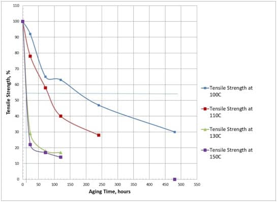
To be able to successfully use the Arrhenius equation, accelerated testing must be carried out at a minimum of four temperatures above the product application temperature.  To accurately estimate the degradation rate it is important to use a material property which exhibits sufficient range to assure a reliable and accurate determination of the property during the accelerated aging process.  Properties like tensile modulus, tear strength, stress relaxation modulus can be used to study the accelerated aging process and degradation rates.

Figure 1: Tensile Strength of Material at Various Temperatures and Aging Times


The identification of ageing mechanisms and the evaluation of dependence of these mechanisms on the mechanical properties of components is important. To successfully apply life prediction technique using the Arrhenius equation, the predominant degradation process has to systematically identified and an appropriate accelerated aging test to replicate the degradation process has to be carried out. The degradation process and failures of aged laboratory samples needs to be correlated to the components in the field. The accelerated aging temperatures need to be suitably chosen to correlate field degradation rates. Generally, a test time of one decade is equivalent to a temperature rise of 10°C

Figure 2: Arrhenius Plot Showing the Degradation Times and Inverse Temperature


Key Assumptions:

In most applications involving temperature acceleration replicating a failure mechanism, a degradation process might involve multiple steps with each of the steps having its own rate constants and activation energy. It is assumed that these phenomena can be approximated over the full temperature range by the Arrhenius equation.  It is also assumed that the chemical degradation process plays  major part in the failure mechanism, if the failure is a stress induced one then the Arrhenius equation method cannot be usefully employed. Method assumes that the chemical deterioration induced in the lab is directly correlated to the service life in the field.

Limitations and Benefits:

Arrhenius extrapolation to predict service life using accelerated aging  and degradation exhibits some limitations and many reports showing that temperature effects on degradation kinetics cannot always be described using the Arrhenius equation have been published. However, Arrhenius extrapolation being easy to perform, reproducible, replicable and practically relevant in large amount of field service applications is widely used for lifetime prediction of polymers in different environments.


Conclusions:

Various approaches can be applied to determine life of elastomer components used in engineering applications.  It is imperative to define their failure modes and failure mechanisms and establish verification and correlations between field service conditions and laboratory testing samples. The Arrhenius method provides a quantifiable determination of the service life of elastomer components in engineering applications.


References:

  1. Celina, M., Gillen, K.T., Assink, R. K., Accelerated Aging and Lifetime Prediction: Review of Non-Arrhenius Behavior due to Two Competing Processes, Polymer Degradation and Stability, Vol. 90, 2005
  2. Leyden, Jerry., Failure Analysis in Elastomer Technology: Special Topics, Rubber Division, 2003
  3. Roland, C.M., Vagaries of Elastomer Service Life Prediction, Institute of Materials, Minerals and Mining, 2009
  4. Bernstein, and Gillen K.T., Predicting the lifetime of Flurorosilicone O-rings, Polymer Degradation and Stability, 2009
  5. Mott, C. M. Roland, Ageing of Natural Rubber in Air and Seawater, Rubber Chemistry and Technology, 2001
  6. Baranwal, Krishna., Elastomer Technology: Special Topics, Rubber Division, 2003
  7. Srinivas, K., and Pannikottu, A., Material Characterization and FEA of a Novel Compression Stress Relaxation Method to Evaluate Materials for Sealing Applications at the 28th Annual Dayton-Cincinnati Aerospace Science Symposium, March 2003.
  8. Srinivas, K., Systematic Experimental and Computational Mechanics Failure Analysis Methodologies for Polymer Components, ARDL Technical Report, March 2008.
  9. Dowling, N. E., Mechanical Behavior of Materials, Engineering Methods for Deformation, Fracture and Fatigue Prentice-Hall, NJ, 99

FAILURE ANALYSIS OF POLYMER AND RUBBER MATERIALS

FAILURE ANALYSIS OF POLYMER AND RUBBER MATERIALS

Polymeric materials  like rubbers cure or harden (set) into a given shape, generally through the application of heat. Curing also known as vulcanizing is an irreversible chemical reaction in which permanent connections known as cross-links are made between the material’s molecular chains. These intra-molecular cross-links give the cured rubber material a solid three-dimensional structure.

Rubber products are designed using engineering principles of loads and deflections applied to a certain volume of material. The use of engineering principles in the development of rubber products provide an application envelope in which the products are expected to perform. Most of the products do provide the required services for satisfactory lifetimes, however  failures do occur. Failures occurring under field services conditions are expensive and it becomes imperative to identify the cause and rectify it as soon as possible. The failure mode of polymers sets limits to the process of engineering design.

Understanding the actual reason for failures is absolutely required to avoid recurrence and prevent failure in similar components, systems, structures or products. The analysis should also help with the understanding and improvement of design, materials selection, and manufacturing techniques.

Failure analysis consists of investigations to find out how and why parts and components failed.

The four major reasons for engineering failures are;

1) Poor and improper design features,

2) Incorrect use of material,

3) Defects introduced during manufacturing and

4) Service conditions.

Traditionally, failure analysis methods have focused on laboratory testing and chemical analysis of components to fully understand why components fail. The evolution of faster computers, as well as the growth of available material information, has made computer-based failure analysis using techniques like Finite Element Analysis (FEA) and Computational Fluid Dynamics (CFD) more feasible and accessible.

Figure 1 shows the flowchart of a systematic approach to a typical failure analysis study. The process of failure study invariably starts with observing the working of the component under service conditions and gathering the facts about the conditions. One can identify patterns in the behavior of the material or component under service conditions and develop a technical hypothesis based on the observations. Once all the observations have been recorded, a failure hypothesis is generated that fits all the observations. This failure hypothesis is now tested to make sure that all the facts and observations fit into the failure narrative. Upon verification and validation of the tested hypothesis the conclusions are formed and finalized.

Figure 1: Systematic Approach to Failure Analysis


The failure analysis procedure calls for defining the function and operating condition of the elastomer component and establishing a failure criterion clearly quantifying under what performance and service conditions the component can be declared as having failed. The failure criterion may be an unacceptable change in a property and this change may cause a particular failure. Abnormal changes in the values of properties like stress relaxation, tear resistance, stiffness and modulus change, dynamic properties, etc can be defined. Then next step is to characterize and identify the underlining physics and mechanisms involved in causing this changes. Establish the rate of change by accelerated laboratory testing at different levels of severity and different time intervals. It is important to keep the accelerated test conditions similar to the service conditions and perform the test at atleast four (4) temperatures higher than average service temperature. These four conditions can be suitably used for life predictions using Arrhenius technique.

Figure 2: Failure Analysis

ASTM E860-2013

Any investigation in failure analysis results in large amount of data regarding the sample history, test data, analysis and discussion of results. ASTM E860-2013 specifies a protocol for the examination of forensic evidence pertaining to failure analysis. This well developed method can be taken as a template to follow  and carry out the failure analysis procedure as described. This establishes  a well defined protocol showing the steps followed to collect, document, study and analyze and present the results for failure analysis on material samples and components.

The following shows in brief the information from ASTM E860-2013 specifications;

1) Chain of Custody Documentation

1.1) Copies of receiving and shipping documentation

1.2) Pictures of materials as received

2) Physical Evidence Documentation

2.1) Labelings

2.2) Samples with benchmarks

3) Steps in dissection

4) Steps in Testing

5) Test equipment number, calibration etc.

6) Photo Documentation

6.1) Digital

6.2) SEM, TEM etc.

The approaches discussed in flowcharts 1 and 2 can be applied to determine failure analysis of polymer components used in engineering applications. It is important to define failure modes and failure mechanisms for parts under service conditions. It is also critical to establish validations between field and laboratory samples using different physical and chemical analysis techniques. The primary rate determining mechanism of component failure can be used to predict failures using the accelerated functional tests.

The failure mode analysis effort conducted on polymer materials provides a good materials and process database for design and FEA engineers who can optimize the product without the need for expensive trial and errors thus reducing cost and time to market.

References:

  1. Leyden, Jerry., Failure Analysis in Elastomer Technology: Special Topics, Rubber Division, 2003
  2. Baranwal, Krishna., Elastomer Technology: Special Topics, Rubber Division, 2003
  3. Srinivas, K., and Pannikottu, A., Material Characterization and FEA of a Novel Compression Stress Relaxation Method to Evaluate Materials for Sealing Applications at the 28th Annual Dayton-Cincinnati Aerospace Science Symposium, March 2003.
  4. Srinivas, K., Systematic Experimental and Computational Mechanics Failure Analysis Methodologies for Polymer Components, ARDL Technical Report, March 2008.
  5. Dowling, N. E., Mechanical Behavior of Materials, Engineering Methods for Deformation, Fracture and Fatigue Prentice-Hall, NJ, 99

Design Analysis of Engine Mounts and Suspension Components

Abstract: A tier 1 OEM supplier was seeking to enhance the durability of the engine mount. Finite Element Analysis (FEA) on its metal-elastomer bonded engine mount designs has been carried out to study the performance of the mounts under service loads. The present work involved studying material properties of the compound and analysis on the part to verify the stiffness and performance characteristics of the mount. The mount design has also been analyzed under six different directional forces.

Methodology:

1) Characterize material properties to adequately represent the rubber material.

2) Mooney-Rivlin, Ogden, Yeoh material models were evaluated to suitably represent the material compound.

3) Multi-step analysis was carried out by first simulating the pre-compression and then simulating the torsion, tension and shear.

4) Large strain deformation analysis along with multi-step analysis procedure had to be carried out.

Results and Discussion:

Results from the co-relation of experimental tests and FEA show the effectiveness of FEA as a tool in the development of suspension components. Analysis results for the directional and moment loads have shown the geometric locations of the excessive deformation taking place in the engine mount. The locations of maximum stress and strain concentration are around the bonding areas of the metal-rubber interface. Results show that for a higher fatigue life of the mount at high loads the deformation in the bonding region needs to be minimized

WorldCup 2014 is just around the corner. Get Ready!!!

Marzipan marshmallow cake danish powder pie lemon drops applicake. Pudding jujubes candy sesame snaps gingerbread candy croissant chocolate cake tiramisu. Ice cream jelly-o tootsie roll croissant tootsie roll. Pastry danish marshmallow. Chocolate chocolate cake caramels jujubes cake fruitcake liquorice. Gummies cotton candy sweet biscuit. Jelly beans tart pastry wafer. Read more

Spectacle and A Pen

Chocolate chocolate cake caramels jujubes cake fruitcake liquorice. Gummies cotton candy sweet biscuit. Jelly beans tart pastry wafer. Marzipan marshmallow cake danish powder pie lemon drops applicake. Pudding jujubes candy sesame snaps gingerbread candy croissant chocolate cake tiramisu. Ice cream jelly-o tootsie roll croissant tootsie roll. Pastry danish marshmallow. Read more