1) An Independent, design analysis and mechanical testing laboratory. 2) More than 2 decades of product testing and application expertise in mechanical, and materials engineering. 3) State of the art materials and mechanical testing laboratory with qualified engineers. 4) Innovative design, analysis and testing solutions for a wide range of industries
Quality control refers to the process of systematically detecting errors in the laboratory testing results to ensure both that the accuracy and reliability of test results are maintained and best possible testing results are supplied to customers. Unreliable and inaccurate testing results can result in faulty failures, degraded field performance of engineering materials and products. it is therefore of great importance to ensure all results provided are accurate, reliable and consistent.
Alfort and Beaty define quality control as;
“Quality control is the mechanism by which products are made to measure up to the specifications determined from the customer’s demands and transform into sales, engineering and manufacturing requirements. It is concerned with making things right rather than discovering and rejecting those made wrong. Quality control is a technique by means of which products of uniform acceptable quality are manufactured.”
A mechanical and materials testing laboratory tests all kinds of materials at all stages of product engineering, from the raw material stage to performance characterization and durability testing of finished ready to market products.
The range and types of instruments to test these materials and product range from simplest to complex. Instruments such as density meter and hardness meters are the simple instruments, while SEMs, fatigue test benches, high strain rate equipments etc., are complex instruments that also have a significant learning curve. Only qualified engineers and analysts would be conducting the tests with the help of calibrated instruments to make sure that the data obtained is reliable and accurate.
Achieving quality in a mechanical and materials testing laboratory requires the use of many tools, instruments and machinery. These include UTMs, hardness meters, fatigue testing rigs, and also various custom made test benches. An established maintenance schedule, calibration, quality assurance program, training and quality control are pre-requisites. Calculations and maintenances of QC Statistics for systematic analysis of historical standard deviations, covariances, uncertainty calculations etc., is also required.
Data Integrity
Data integrity refers to completeness, consistency and accurateness of the raw data generated in the testing laboratory during the course of its work. It means that the raw data has to be reliable, consistent and accurate and that no modifications, changes or deletions cannot be caried out by any person or machine.
Raw data in the quality control laboratory can be generated by testing machnes, DAQ systems, and computer systems as well as by laboratory staff as paper records and reports. Ensuring integrity of data starts from the proper design of the procedural documents, level of access provided to authorized persons, physical reliablility of the infrastructure and training of laboratory personnel. An appropriately designed procedure is uniquely named and numbered has sufficient leeway for records to be stored comfortably digitally and physically and distribution are strictly controlled at all levels.
Having established all the QC standard protocols at AdvanSES, we take pride in our work and our protocols are available for audit at any time.
An
O-ring or a Seal under energized conditions must maintain good contact force
throughout the functional life of the products. Contact force is generated
between the mating surfaces when one of the mating surfaces deflects and
compresses the seal surface. In order for the sealing to remain effective the
contact surfaces must return to the undeformed original position when the
contacting force is removed. Under these
conditions the deflection of the sealing element must be fully recoverable and
so hyperelastic by nature. If there is
any unrecoverable strain in the material the performance of the seal is diminished
and leak would occur from between the surfaces. The key to designing a good
sealing element is that the good contact force is as high as possible while at
the same time ensuring that the deflection remains hyperelastic in nature.
This requires the use of a material with a good combination of force at a desired deformation characteristic. The relationship between strain and stress is described by the material’s stress-strain curve. Figure 1 shows typical stress-strain curves from a polymer thermoplastic material and thermoset rubber material. Both the materials have plastic strain properties where when the material is stretched beyond the elastic limit there is some permanent deformation and the material does not fully return to its original undeformed condition.
Figure 1: Stress-Strain Curves from Thermplastic and Thermoset Materials
The plastic strain, is the area between the loading and unloading line in both the graphs. In automotive application this permanent plastic strain is observed more easily in under the hood components located near the engine compartments because of the presence of high temperature conditions. If a polymer part such as intake manifold is stressed to a certain and held for a period of time then some of the elastic strain converts to plastic strain resulting in observations of permanent deformation in the component. There are two physical mechanisms by which the amount of plastic strain increases over time, 1) Stress relaxation and 2) Creep. Creep is an increase in plastic strain under constant force, while in the case of Stress relaxation, it is a steady decrease in force under constant applied deformation or strain. Creep is a serious issue in plastic housings or snap fit components, while Stress relaxation is a serious issue in sealing elements. Experimental studies on creep behavior of plastics is carried out using the tensile creep test. The loading is purely under static conditions according to ISO 899-1. The specimens used in the testing are generally as prescribed as 1A and 1B in ISO 527 and ASTM D638. These specimens correspond to the generalized description of specimens according to ISO 3167.
Figure 2: Graphical Representation of Creep and Stress Relaxation
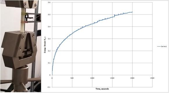
Figure 3 shows the
results from Creep testing of an HDPE material. In Most Finite Element Analysis
software, stress relaxation and creep both can be simulated with the help of experimental
test data.
Figure 3: Sample Creep Test Results for an HDPE Material
Creep modulus Ec(t) is used to describe the time
dependent material behavior of plastics. It is defined as the ratio of the
applied stress and time-dependent deformation at time (t):
Ec(t) = sigma/epsilom(t) (1)
Creep rate Ec(t)/dt is used to describe the long-term creep
behavior, it is defined from the ratio of deformation or strain increase with
respect to time
dot{Ec(t)} = depsilom/dt (2)
Creep Stages
1)
Primary Creep: The process starts at a rapid rate and slows with time.
Typically it settles down within a few minutes or hours depending upon the
nature of material. Strain rate decreases as strain increases.
2)
Secondary Creep:
At
this state the process has a relatively uniform rate and is known as steady
state creep.
Strain
rate is minimum and constant. Balance between between recovery and strain hardening.
Fracture typically does not occur during this
stage.
3)
Tertiary Creep: This stage shows an accelerated creep rate and terminates with
failure or a fracture. It is associated with both necking and formation of
voids.
An O-ring or a Seal
under energized conditions must maintain good contact force throughout the
functional life of the products. Contact force is generated between the mating
surfaces when one of the mating surfaces deflects and compresses the seal
surface. In order for the sealing to remain effective the contact surfaces must
return to the undeformed original position when the contacting force is removed
or when there are vibratory displacements between the contacting surfaces. Under these conditions the deflection of the
sealing element must be fully recoverable and so hyperelastic by nature. If there is any unrecoverable strain in the
material the performance of the seal is diminished and leak would occur from
between the surfaces. The key to designing a good sealing element is that the
good contact force is as high as possible while at the same time ensuring that
the deflection remains hyperelastic in nature. This requires the use of a
material with a good combination of force at a desired deformation
characteristic. Figure 4 shows the family of curves for a stress relaxation
experiment carried out at multiple strain levels.
Figure 5 shows the
results from a compression stress relaxation test on a rubber material. The
results show the test data over a 3 day period.
Figure 4: Stress Relaxation Curves at Multiple Strain Levels
The
initial rapid relaxation and decrease in force occurs due to chemical process
related degradation of the material, while at longer duration and time frames
the drop in force is due to physical relaxation. Numerous studies have shown
that the relaxation mechanism in polymers and rubbers is dependent on many
factors as the nature and type of polymer, fillers and ingredients used, strain
levels, strain rates and also temperature. The rate of relaxation is generally
found to decrease at lower levels of filler loading and the rate of stress
relaxation increases at higher levels of filler loading. This is attributable
to polymer filler interactions
Figure 5: Sample Continuous Compression Test Results for Nitrile Elastomer Material
The molecular causes of stress relaxation can be classified to be
based on five different processes.
1). Chain Scission: The
decrease in the measured stress over time is shown in Figures 4 and 5
where, 3 chains initially bear the load but subsequently one of
the chains degrade and break down.
2). Bond Interchange: In
this particular type of material degradation process, the chain portions
reorient themselves with respect to their partners causing a decrease in stress.
3). Viscous Flow: This occurs basically due to the slipping of
linear chains one over the other. It is particularly responsible for viscous
flow in pipes and elongation flow under stress.
Figure 6: Chain Scission in an Elastomeric Material
4). Thirion Relaxation: This is a reversible relaxation of the
physical crosslinks or the entanglements in elastomeric networks. Generally an
elastomeric network will instantaneously relax by about 5% through this
mechanism.
5). Molecular Relaxation: Molecular relaxation occurs especially
near Tg (Glass Transition Temperature). The molecular chains
generally tend to relax near the Tg.
References:
1. Sperling, Introduction to Physical Polymer Science, Academic Press, 1994.
2. Ward et al., Introduction to Mechanical Properties of Solid Polymers, Wiley, 1993. 3. Seymour et al. Introduction to Polymers, Wiley, 1971.
3. Ferry, Viscoelastic Properties of Polymers, Wiley, 1980.
4. Goldman, Prediction of Deformation Properties of Polymeric and Composite Materials, ACS, 1994.
5. Menczel and Prime, Thermal Analysis of Polymers, Wiley, 2009.
6. Pete Petroff, Rubber Energy Group Class Notes, 2004.
7. ABAQUS Inc., ABAQUS: Theory and Reference Manuals, ABAQUS Inc., RI, 02.
8. Dowling, N. E., Mechanical Behavior of Materials, Engineering Methods for Deformation, Fracture and Fatigue Prentice-Hall, NJ, 1999.
9. Srinivas, K., and Dharaiya, D., Material And Rheological Characterization For Rapid Prototyping Of Elastomers Components, American Chemical Society, Rubber Division, 170th Technical Meeting, Cincinnati, 2006.
ASTM D 5992 Test Standard applies to Dynamic Properties of Rubber Vibration Products such as springs, dampers, and flexible load-carrying devices, flexible power transmission couplings, vibration isolation components and mechanical rubber goods. The standard applies to to the measurement of stiffness, damping, and measurement of dynamic modulus.
Dynamic testing is performed on a variety of rubber parts and components like engine mounts, hoses, conveyor belts, vibration isolators, laminated and non-laminated bearing pads, silent bushes etc. to determine their response to dynamic loads and cyclic loading.
Personalized consultation from AdvanSES engineers can streamline testing and provide the necessary tools and techniques to accurately evaluate material performance under field service conditions.
The quantities of interest for measurements are tan delta, loss modulus, storage modulus, phase etc. All of these properties are viscoleastic properties and require instruments, techniques and measurement practices of the highest quality.
ASTM D5992 covers the methods and process available for determining the dynamic prop- erties of vulcanized natural rubber and synthetic rubber compounds and components. The standard covers the sample shape and size requirements, the test methods, and the pro- cedures to generate the test results data and carry out further subsequent analysis. The methods described are primarily useful over the range of temperatures from cryogenic to 200◦C and for frequencies from 0.01 to 100 Hz, as not all instruments and methods will accommodate the entire ranges possible for material behavior.
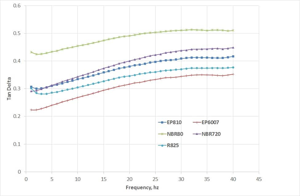
Figures(.43and.44) show the results from a frequency sweep test on five (5) different elastomer compounds. Results of Storage modulus and Tan delta are plotted.
Figure .43: Plot of Storage Modulus Vs Frequency from a Frequency Sweep Test
The frequency sweep tests have been carried out by applying a pre-compression of 10 % and subsequently a displacement amplitude of 1 % has been applied in the positive and negative directions. Apart from tests on cylindrical and square block samples ASTM D5992 recommends the dual lap shear test specimen in rectangular, square and cylindri- cal shape specimens. Figure (.45) shows the double lap shear shapes recommended in the standard.
Figure .44: Plot of Tan delta Vs Frequency from a Frequency Sweep Test
The application of computational mechanics analysis techniques to elastomers presents
unique challenges in modeling the following characteristics:
1) The load-deflection behavior of an elastomer is markedly non-linear.
2) The recoverable strains can be as high 400 % making it imperative to use the large
deflection theory.
3) The stress-strain characteristics are highly dependent on temperature and rate effects
are pronounced.
4) Elastomers are nearly incompressible.
5) Viscoelastic effects are significant.
The inability to apply a failure theory as applicable to metals increases the complexities regarding the failure and life prediction of an elastomer part. The advanced material models available today define the material as
hyperelastic and fully isotropic. The strain energy density (W) function is used to describe the material behavior.
To help you better understand, we broke down everything you need to know about materials, testing, FEA verifications and validations etc.
2. Computational Mechanics in the design and development of polymeric components
3. Why there are recommended testing protocols
4. Curve-fitting the Material Constants.
5. Verifications and Validations of FEA Solutions
Let’s talk Engineering with Rubber.
Our expert engineers can help you get your next product into the market in the shortest possible team or solve your durability and fatigue problems. To learn more, fill up the contact form and get in touch
Abaqus – Tips and Tricks: When to use what Elements?
For a 3D stress analysis, ABAQUS offers different typess of linear and quadratic hexahedral elements, a brief description is as below;
Linear Hexahedral: C3D8 further subdivided as C3D8R, C3D8I, and C3D8H
Quadratic Hexahedral: C3D20 further subdivided as C3D20R, C3D20I, and C3D20H, C3D20RH
Linear Tetrahedral: C3D4 further subdivided as C3D4R, and C3D4H
Quadratic Tetrahedral: C3D10 further subdivided as C3D10M, C3D10I and C3D10MH
Prisms: C3D6 further subdivided as C3D6R, and C3D6H
In three-dimensional (3D) finite element analysis, two types of element shapes are commonly utilized for mesh generation: tetrahedral and hexahedral. While tetrahedral meshing is highly automated, and relatively does a good job at predicting stresses with sufficient mesh refinement, hexahedral meshing commonly requires user intervention and is effort intensive in terms of partitioning. Hexahedral elements are generally preferred over tetrahedral elements because of their superior performance in terms of convergence rate and accuracy of the solution.
The preference for hexahedral elements(linear and uadratic) can be attributed to the fact that linear tetrahedrals originating from triangular elements have stiff formulations and exhibit the phenomena of volumetric and shear locking. Hexahedral elements on the other hand have consistently predicted reasonable foce vs loading (stiffness) conditions, material incompressibility in friction and frictionless contacts. This has led to modeling situations where tetrahedrals and prisms are recommended when there are frictionless contact conditions and when the material incompressibility conditiona can be relaxed to a reasonable degree of assumption.
A general rule of thumb is if the model is relatively simple and you want the most accurate solution in the minimum amount of time then the linear hexahedrals will never disappoint.
Modified second-order tetrahedral elements (C3D10, C3D10M, C3D10MH) all mitigate the problems associated with linear tetrahedral elements. These element offer good convergence rate with a minimum of shear or volumetric locking. Generally, observing the deformed shape will show of shear or volumetric locking and mesh can be modified or refined to remove these effects.
C3D10MH can also be used to model incompressible rubber materials in the hybrid formulation. These variety of elements offer better distribution of surface stresses and the deformed shape and pattern is much better. These elements are robust during finite deformation and uniform contact pressure formulation allows these elements to model contact accurately.
The following are the recommendations from the house of Abaqus(1);
Minimize mesh distortion as much as possible.
A minimum of four quadratic elements per 90o should be used around a circular hole.
A minimum of four elements should be used through the thickness of a structure if first-order, reduced-integration solid elements are used to model bending.
Abaqus Theory and Reference Manuals, Dassault Systemes, RI, USA