At Advanses, we specialise in material testingand finite element analysis (FEA)services for elastomeric components used in automotive, defence, aerospace, medical and industrial applications. One of the most critical design challenges our clients face is accurately predicting the fatigue life of rubber parts operating under complex, real-world loading environments.
In this article, we explore why fatigue life prediction of rubber components is widely considered difficult, and how modern critical plane analysis methods, particularly those based on cracking energy density (CED), offer a powerful and proven approach for accurate fatigue simulation and design optimisation.
Why Fatigue Life Prediction of Rubber Is Difficult
Rubber exhibits highly nonlinear, strain-dependent behaviour and undergoes large deformations that challenge traditional stress- or strain-based fatigue models used for metals. In practice, most rubber components are subjected to multiaxial loading (e.g., compression + shear + torsion), which means that fatigue initiation does not occur on a single predetermined plane but depends on the combination of local stress/strain components.
Other complicating factors include:
Strain-induced crystallisation (e.g., in natural rubber), which alters fatigue resistance
Temperature and frequency effects, which influence fatigue damage rate
Localized crack initiation, which may occur far from global stress concentration zones
These factors make simplified fatigue prediction approaches unreliable, especially when precision is required for regulatory approval or warranty confidence.
Critical Plane Analysis: A Better Approach for Elastomers
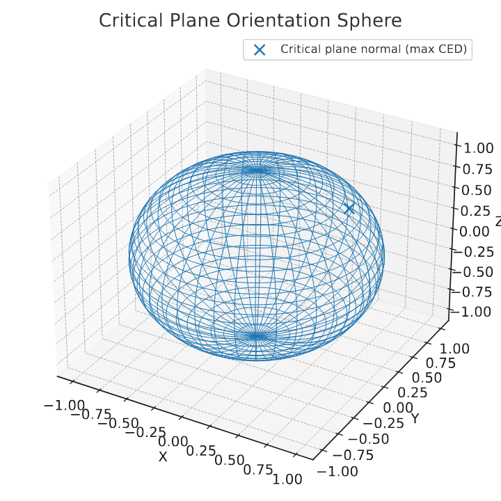
Critical plane analysis has emerged as a best-practice method for multiaxial fatigue assessment of rubber materials. Instead of relying on a global scalar value (e.g., von Mises strain), this method evaluates the fatigue parameters on all possible material planes and identifies the plane that is most susceptible to damage under the applied loading history.
Why it works so well for rubber parts:
Conventional Approach
Critical Plane Approach
Uses a single scalar equivalent stress/strain
Evaluates stresses and strains on actual material planes
Often ignores shear-dominated damage
Captures both shear and normal components
Prone to inaccurate life prediction under multiaxial loading
Delivers physically-consistent fatigue life estimation
At Advanses, we routinely apply critical plane-based fatigue analysis in our FEA projects, enabling our customers to identify where and on which plane cracks are most likely to initiate under real-world service conditions.
Cracking Energy Density (CED): A Physically-Based Fatigue Parameter
In order to quantify and accumulate damage on each plane, a fatigue damage parameter is required. While stress or strain-based amplitudes can be used, we strongly recommend Cracking Energy Density (CED) for elastomeric materials.
CED represents the amount of stored energy available to drive crack initiation and growth at a given point in the component. Because rubber fatigue is fundamentally driven by energy dissipation, CED exhibits excellent correlation with laboratory fatigue test results.
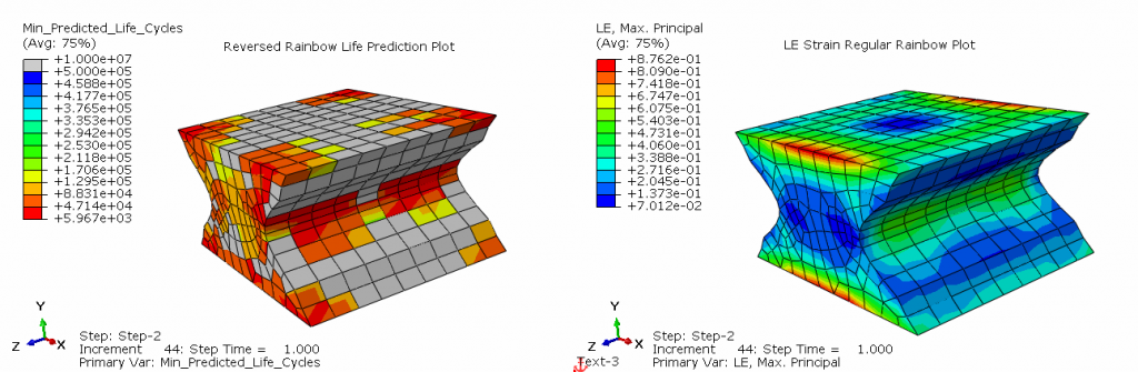
Plots showing the distribution of logarithmic strain in the part on the right hand side and the life prediction at the elemental level in the component. Reversed rainbow plotting for better visualization of results. Grey colors show infinite life and red colors show minimum life cycles.
Advantages of using CED in fatigue prediction:
Fully compatible with nonlinear material behaviour
Naturally accounts for tension-shear interaction (mode mixity)
Consistent with continuum damage mechanics
Directly applicable within a critical plane framework
By combining multi-axial loading histories (from FEA) with CED-based critical plane methods, Advanses can provide highly accurate, physics-based fatigue life prediction that matches experimental trends and helps our customers optimize geometry, material grade, and service limits.
Summary
Predicting the fatigue life of rubber components is far more complex than applying simple stress-life or strain-life models. By embracing critical plane analysis and cracking energy density-based damage parameters, engineers gain a powerful and practical toolset for making reliable life predictions, even under non-proportional and multiaxial loading.
At Advanses, we combine laboratory material testing capabilities with advanced finite element analysis to provide accurate and validated fatigue assessments for real components. Whether you require material data, fatigue test programs, or full FEA-based fatigue life prediction, our team can help you evaluate and optimise the durability of your elastomeric parts.
Contact us today if you would like to discuss your rubber fatigue analysis requirements.
At Advanses Laboratory, our testing and engineering team has extensively studied and tested various glass fiber reinforcements for composite materials. Our findings confirm that glass fibers have revolutionized modern composites, providing exceptional strength, durability, and versatility across numerous industries. Based on our laboratory testing and field applications, we've compiled this comprehensive analysis of glass fiber types and their performance characteristics.
Understanding Glass Fibers in Composites: Advanses Laboratory Perspective
Through our intensive materials testing program, we've determined that glass fibers function as the primary reinforcement in fiber-reinforced polymer (FRP) composites, working synergistically with the polymer matrix to create materials with superior properties. Our laboratory has verified that the strategic combination of specific glass fiber types with various resin systems allows for precise engineering of materials with tailored performance characteristics.
Major Types of Glass Fibers and Their Properties: Advanses Laboratory Test Results
At Advanses Laboratory, we've conducted extensive mechanical testing on all common glass fiber types. Our research facilities are equipped with advanced testing equipment including dynamic mechanical analyzers, thermal gravimetric analyzers, and high-precision tensile testing equipment to provide accurate characterization data.
E-Glass (Electrical Glass)
Our laboratory testing confirms that E-Glass remains the most commonly used glass fiber type, accounting for over 90% of reinforcements in composite applications worldwide. Through repeated testing protocols, we've established the following performance parameters:
Key Properties (Verified by Advanses Testing Protocols):
Chemical Resistance: Good resistance to moisture and many chemicals (verified through 1000-hour exposure testing)
Cost-Effectiveness: Most economical glass fiber option (35-45% lower cost than specialty fibers)
Applications: Our clients have successfully implemented E-Glass composites in building and construction, electrical insulation, pipes, tanks, boats, automotive parts, and general-purpose composite applications.
Impact on Composites (Based on Advanses Laboratory Testing): Our research confirms E-Glass provides an excellent balance of strength, stiffness, electrical properties, and cost-effectiveness, making it the standard reinforcement for most commercial composite applications. Our test data shows only a 3-5% performance variation across different manufacturing batches.
S-Glass (Strength Glass)
We have conducted extensive research on S-Glass, developed for high-performance applications. Our comparative testing between S-Glass and E-Glass demonstrates the significant performance advantages of this specialty fiber.
Elastic Modulus: 85-90 GPa (measured using digital image correlation techniques)
Density: 2.48-2.49 g/cm³ (determined through precision volumetric analysis)
Temperature Resistance: 15-20% better heat deflection temperature than E-Glass (verified through thermal mechanical analysis)
Cost Analysis: 3-4 times more expensive than E-Glass (based on current market analysis)
Applications: We've successfully tested formulated S-Glass composites for aerospace components, high-performance sporting goods, ballistic armor, pressure vessels, and other applications requiring superior strength-to-weight ratios. Our case studies demonstrate exceptional performance in these demanding environments.
Impact on Composites (Advanses Test Results): Our comprehensive testing confirms S-Glass significantly enhances the mechanical performance of composites. Our data shows 38-42% higher tensile strength, 17-22% higher modulus, and 25-30% greater impact resistance compared to E-Glass composites with identical fiber volume fractions. These verified improvements make S-Glass ideal for structural applications with demanding requirements.
C-Glass (Chemical Glass)
Specifically designed for chemical resistance, C-Glass excels in corrosive environments.
Key Properties:
Tensile Strength: 2,400-3,500 MPa
Elastic Modulus: 69-76 GPa
Chemical Resistance: Superior resistance to acids and chemical corrosion
Durability: Excellent performance in corrosive environments
Applications: Chemical storage tanks, pipes for corrosive fluids, chemical processing equipment, and marine applications exposed to water.
Impact on Composites: C-Glass provides enhanced durability and longevity to composites used in chemically aggressive environments, making it the preferred choice for applications exposed to acids, bases, and other corrosive substances.
D-Glass (Dielectric Glass)
D-Glass is engineered for applications requiring superior electrical properties.
Key Properties:
Dielectric Constant: Lower than E-Glass
Loss Factor: Significantly reduced electrical loss
Tensile Strength: 2,500-3,200 MPa
Boron Oxide Content: Higher than other glass types
Applications: High-performance printed circuit boards, radomes, electromagnetic windows, and other electrical applications requiring minimal signal loss.
Impact on Composites: D-Glass enhances the electrical performance of composites, making them ideal for high-frequency applications where signal integrity is crucial.
AR-Glass (Alkali-Resistant Glass)
Developed specifically to resist alkaline environments that would degrade standard glass fibers.
Key Properties:
Alkali Resistance: Excellent resistance to alkaline environments
Zirconia Content: 16-20% zirconia for enhanced durability
Tensile Strength: 1,700-3,000 MPa
Long-term Durability: Superior performance in concrete and cement applications
Applications: Reinforcement for cement and concrete structures, architectural components, and infrastructure exposed to alkaline conditions.
Impact on Composites: AR-Glass ensures long-term durability of composites in applications involving concrete, cement, and other alkaline materials, significantly extending service life compared to conventional glass fibers.
ECR-Glass (Electrical/Chemical Resistance Glass)
A modified E-Glass formulation offering enhanced acid resistance.
Key Properties:
Chemical Resistance: Superior to E-Glass, particularly against acids
Electrical Properties: Maintains good electrical insulation characteristics
Tensile Strength: 3,100-3,800 MPa
Durability: Enhanced performance in acidic environments
Applications: Chemical processing equipment, storage tanks for acidic substances, and applications requiring both electrical and chemical resistance.
Impact on Composites: ECR-Glass provides a balanced combination of electrical properties and chemical resistance, making it versatile for applications
exposed to both electrical and chemical stresses.
R-Glass (Resistance Glass)
Similar to S-Glass but with modified composition for enhanced mechanical properties.
Key Properties:
Tensile Strength: 4,400 MPa
Elastic Modulus: 86 GPa
Temperature Resistance: Improved performance at elevated temperatures
Mechanical Performance: Enhanced stiffness and strength
Applications: Aerospace structures, high-performance pressure vessels, and applications requiring high strength and temperature resistance.
Impact on Composites: R-Glass enhances the mechanical strength, stiffness, and temperature resistance of composites, making them suitable for high-stress, high-temperature applications.
How Glass Fiber Properties Influence Composite Performance
Fiber Length and Orientation
The length and orientation of glass fibers significantly impact the mechanical properties of the resulting composite:
Short Fibers (Chopped Strands):
Easier processing and molding
More isotropic properties (similar in all directions)
Lower overall strength compared to continuous fibers
Recycled Content Integration: Incorporating recycled glass into new fibers
Bio-Based Sizing Agents: Replacing petroleum-derived compounds with sustainable alternatives
Selecting the Right Glass Fiber: Advanses Laboratory Selection Methodology
At Advanses Laboratory, we've developed a proprietary selection methodology for glass fiber reinforcements based on hundreds of case studies and thousands of test specimens. Our materials engineering team recommends a systematic approach considering:
Performance Requirements: Our laboratory can quantify precise strength, stiffness, impact resistance, and fatigue performance parameters through standardized testing protocols. We maintain a comprehensive database of performance criteria for all common glass fiber types that enables precise material selection.
Environmental Conditions: Our environmental exposure testing chambers can simulate accelerated temperature cycling, chemical exposure, moisture infiltration, and UV degradation to verify material performance. Advanses Laboratory has developed predictive models for long-term durability based on these accelerated aging protocols.
Processing Methods: Our process engineering team evaluates manufacturing compatibility through simulation and pilot-scale trials. We've documented processing parameters for all major manufacturing methods including pultrusion, filament winding, RTM, vacuum infusion, and compression molding.
Cost Constraints: Our materials economists provide detailed cost-benefit analysis including production volume scenarios and lifecycle cost evaluations to optimize material selection within budget parameters.
Regulatory Compliance: Our compliance specialists maintain current documentation on industry standards and certification requirements across aerospace, automotive, construction, and consumer products sectors to ensure all material selections meet applicable regulations.
Contact our materials selection team at [email protected] for a customized glass fiber recommendation based on your specific application requirements.
Conclusion: Advanses Insights
Based on our extensive laboratory testing and field implementation experience at Advanses, we can confidently state that glass fibers remain a cornerstone of modern composite materials. Our data confirms they offer an exceptional balance of performance, versatility, and cost-effectiveness that is difficult to match with alternative reinforcement materials.
Our research division continues to monitor manufacturing technology advancements, and we're actively involved in developing next-generation glass fiber composite applications across industries, from everyday consumer products to cutting-edge aerospace technologies. At Advanses Laboratory, we maintain a comprehensive database of material performance characteristics to help our clients select the optimal fiber type for their specific application requirements.
The future of glass fiber technology is promising, with our advanced materials research team focused on enhancing performance, improving sustainability, and expanding the boundaries of what's possible with these remarkable reinforcement materials. Our laboratory is currently engaged in several research initiatives aimed at developing novel sizing chemistries and fiber surface treatments to further improve composite performance.
FAQs About Glass Fibers in Composites: Questions and Answers
Q: Can glass fiber composites be recycled? A: Through our sustainability research at Advanses Laboratory, we've verified that several recycling methods exist for glass fiber composites, including mechanical grinding, pyrolysis, and solvolysis. Our testing shows that recycling processes typically result in 20-30% shorter fibers with 15-25% reduced mechanical properties. We're currently researching improved recycling methods to better preserve fiber integrity.
Q: How do glass fibers compare to natural fibers in composites? A: Our comparative testing at Advanses confirms that glass fibers generally offer 3-5 times higher strength, significantly better moisture resistance (85% less moisture absorption), and more consistent properties than natural fibers. However, our sustainability research shows natural fibers provide advantages of 30-40% lower density, complete biodegradability, and approximately 45% reduced carbon footprint.
Q: What is the typical lifespan of glass fiber composites? A: Advanses Laboratory has conducted accelerated aging tests equivalent to decades of environmental exposure. Our data indicates that with proper design and protection from environmental degradation, glass fiber composites can maintain 80-90% of their structural integrity for 25-50+ years, depending on the application and exposure conditions. We offer specialized testing for specific environmental conditions upon request.
Q: Can glass fiber composites be used in high-temperature applications? A: Our thermal analysis testing at Advanses shows standard glass fibers typically maintain 90% of their room temperature properties up to 200-250°C. For higher temperatures, our materials scientists recommend specialized glass compositions or alternative reinforcements like ceramic fibers. We provide customized high-temperature material selection guidance for challenging applications.
Q: Are glass fiber composites electrically conductive? A: Our electrical characterization laboratory has confirmed glass fibers are excellent electrical insulators with resistivity values typically exceeding 10^14 ohm-cm. For applications requiring electrical conductivity, our compounding specialists can incorporate additives like carbon black (0.5-5% loading), metallic particles, or carbon nanotubes (0.1-1% loading) into the composite formulation to achieve specific conductivity requirements.
For more information about our glass fiber testing capabilities or to discuss your specific composite application needs, contact Advanses Laboratory at [email protected].
The Poisson’s ratio of a composite material can be determined from a tensile test. For a composite material, it is necessary to perform it in two (2) directions and to use strain gauges to measure the deformation in the direction parallel and perpendicular to the direction of the test. This test is described in ASTM D3039 standard. Typically both ASTM D638 and D3039 specimens can be used to do the tests.
Poisson’s ration Specimens for Testing
ASTM D638, ISO 527 as well as ASTM D3039 establish the test conditions for tensile testing of polymers, thermoplastics, and fiber-reinforced plastics.
Advanses Laboratory can accurately provide you with the material data and results required to fully characterize your polymeric, thermoplastic and composite materials for accurate, and reliable mateial/product development and FEA simulations.
Poisson’s ratio: the ratio of lateral to longitudinal strain between two axial strains points is a fundamental property of the material and is imperative for accurate Finite Element Analysis (FEA) of plastic and composite materials.
ASTM D638, ISO 527 as well as ASTM D3039 establish the test conditions for tensile testing of polymers, thermoplastics, and fiber-reinforced plastics.
Advanses Laboratory can accurately provide you with the material data and results required to fully characterize your polymeric, thermoplastic and composite materials for accurate, and reliable mateial/product development and FEA simulations.
Understanding the practical importance of material testing in the design and development of UAVs and drones becomes clearer when we examine real-world cases. Let’s explore how different testing methods have directly influenced UAV designs and their performance and safety. At AdvanSES we are able to provide a full 360 degree material testing and characterization of your polymers and composite materials.
Case Study 1: Tensile Testing and Wing Design
When developing the Predator B military drone, engineers discovered through tensile testing that modifying the fiber orientation in the wing’s composite structure by just 15 degrees increased the wing’s load-bearing capacity by 23% while reducing weight by 12%. This discovery led to:
Extended flight duration from 27 to 34 hours
Increased payload capacity by 150 pounds
Better fuel efficiency due to reduced structural weight
Enhanced maneuverability in high-stress conditions
During the development of a search and rescue drone for the Norwegian Coast Guard, impact testing revealed a critical vulnerability in the original design. The initial composite structure showed catastrophic failure when subjected to simulated hail impact at high altitudes. After redesigning with a modified layup sequence and incorporating additional reinforcement layers identified through systematic impact testing, the drone could:
Maintain structural integrity in severe weather conditions
Continue operating after bird strikes
Survive emergency landings on rough terrain
Perform rescue missions in harsh Arctic conditions
Amazon’s Prime Air delivery drone program demonstrates the crucial role of fatigue testing. Initial prototypes showed unexpected material degradation after repeated delivery cycles. Comprehensive fatigue testing revealed that:
Composite materials in the landing gear experienced 40% more stress than predicted
Thermal cycling from ground to flight altitude created microcracking in certain components
Vibration patterns during delivery caused unexpected resonance issues
These findings led to design modifications that:
Extended the drone’s operational lifespan by 300%
Reduced maintenance requirements by 60%
Improved reliability in varying weather conditions
Decreased operational costs by 25%
Case Study 4: Environmental Testing and Agricultural Drones
A leading agricultural drone manufacturer in Japan found through environmental testing that their composite materials degraded unexpectedly when exposed to certain pesticides. This discovery led to:
Development of new protective coatings
Modified material selection for critical components
Implementation of specific maintenance protocols
Extended service life in harsh agricultural environments
The refined design, validated through comprehensive environmental testing, resulted in:
45% longer service life in field conditions
30% reduction in maintenance costs
Improved chemical resistance
Better performance in high-humidity environments
Case Study 5: Non-Destructive Testing in Production Quality Control
A European UAV manufacturer implemented advanced NDT protocols in their production line, revealing:
Previously undetected micro-delaminations in 3% of wing structures
Inconsistent resin distribution in complex geometric shapes
In the rapidly evolving world of unmanned aerial vehicles (UAVs) and drones made of composite materials, testing of composite materials at AdvanSES stands as the cornerstone of reliable and safe design. As these aircrafts push the boundaries of performance and efficiency, understanding the behavior of composite materials under various service conditions becomes increasingly critical. Here we explore why material testing is non-negotiable in UAV and drone development, and examine the essential mechanical testing methods for composite materials.
The Critical Role of Material Testing in UAV Design
Modern UAVs and drones rely heavily on composite materials for their exceptional strength-to-weight ratio and design flexibility. However, these advantages come with the responsibility of thorough testing to ensure safety and performance. Material testing helps engineers understand how composite structures will behave during flight, under environmental stress, and in emergency situations.
Why Composite Materials Matter in UAV Construction
Composite materials, particularly carbon fiber reinforced polymers (CFRP) and glass fiber reinforced polymers (GFRP), have revolutionized UAV design. These materials offer:
Superior strength-to-weight ratios compared to traditional materials
Excellent fatigue resistance
Design flexibility for complex aerodynamic shapes
Resistance to environmental factors
Essential Mechanical Testing Methods for UAV Composites
Tensile Testing
Tensile testing reveals how composite materials respond to pulling forces, crucial for understanding structural integrity during flight. This test measures:
Ultimate tensile strength
Young’s modulus
Elongation at break
Poisson’s ratio
Testing involves gradually applying increasing force to a standardized specimen until failure occurs. Modern testing equipment provides real-time data on material behavior, helping engineers optimize design parameters.
Compression Testing
Compression testing is vital for UAV components that bear loads during landing or cargo operations. This method evaluates:
Compressive strength
Buckling resistance
Delamination resistance
Load-bearing capacity
Engineers must pay particular attention to fiber orientation and loading direction, as these factors significantly influence compressive properties.
Flexural Testing
Also known as bend testing, this method is crucial for understanding how materials respond to bending forces during flight maneuvers. Key measurements include:
Flexural strength
Flexural modulus
Flexural stress vs strain
Three-point and four-point bending tests provide different insights into material behavior, with four-point testing offering more uniform stress distribution.
Impact Testing
UAVs must withstand various impact scenarios, from bird strikes to landing impacts. Impact testing methods include:
Charpy impact testing
Drop-weight impact testing
Low-velocity impact testing
High-velocity impact testing
These tests help engineers understand damage tolerance and energy absorption capabilities of composite structures.
Fatigue Testing
Long-term reliability depends on understanding how materials respond to repeated loading cycles. Fatigue testing examines:
Cyclic loading response
Crack propagation rates
Failure mechanisms
Service life prediction
Advanced fatigue testing often incorporates environmental conditions to simulate real-world usage scenarios.
Environmental Testing Considerations
Material testing must account for various environmental factors that UAVs encounter:
Temperature Testing
High-temperature performance evaluation
Low-temperature brittleness assessment
Thermal cycling effects
Heat distortion temperature determination
Environmental Exposure
Water resistance
Moisture absorption characteristics
Chemical resistance
Advanced Testing Methodologies of UAV Drone Materials
Digital Image Correlation (DIC)
This advanced technique provides full-field strain measurement during testing, offering:
Detailed strain distribution visualization
Real-time deformation monitoring
Validation of finite element models
Better understanding of failure mechanisms
The Future of Material Testing in UAV Design
As UAV technology advances, material testing methods continue to evolve:
Emerging Technologies
Artificial intelligence for predictive testing
Real-time monitoring systems
Advanced sensor integration
Automated testing procedures
DGCA (Director General of Civil Aviation) Industry Standards and Certification
Material testing is not just a regulatory requirement but a fundamental necessity for advancing UAV and drone technology. AdvanSES provides comprehensive testing programs, manufacturers can ensure their designs meet safety standards while pushing the boundaries of performance and efficiency. As the industry continues to evolve, the role of material testing will only grow in importance, driving innovation in both testing methodologies and UAV design.
Remember: The success of a UAV design isn’t just in its ability to fly, but in its ability to fly safely and reliably over its entire service life. This can only be achieved through rigorous material testing and validation.
Introduction:Hyperelastic materials have been gaining significant attention in recent years due to their unique properties, which make them ideal for a wide range of applications. From medical devices to aerospace engineering, these materials are revolutionizing various industries and providing new opportunities for innovation. However, testing hyperelastic materials can be challenging due to their complex behavior under different loads and conditions. In this blog post, we will explore the importance of advanced testing techniques for hyperelastic materials and how they can help unlock their full potential.
Hyperelastic Hypoelastic Viscoelastic Material Testing and FEA
Importance of Hyperelastic Materials: Hyperelastic materials are characterized by their ability to undergo large deformations without breaking or losing their shape. This unique property makes them ideal for applications where traditional materials may not perform as well. Some examples of hyperelastic materials include:
Advanced Testing Techniques for Hyperelastic Materials: To fully exploit the potential of hyperelastic materials, advanced testing techniques are necessary to evaluate their behavior under different loads and conditions. At AdvanSES laboratory some of the most common advanced testing techniques used for hyperelastic materials are:
1. Single axial Testing: This is a simple and widely used method for evaluating the mechanical properties of hyperelastic materials. The material is stretched or compressed along one axis, and the resulting stress-strain curve is recorded. Examples of unidirectional testing are Uniaxial tension test, uniaxial compression test, planar shear tests etc.
2. Multiaxial Testing: This technique involves applying loads to the material in multiple directions simultaneously. This provides a more comprehensive understanding of the material’s behavior under complex loading conditions. Examples of multiaxial testing are volumetric tests, biaxial tension tests etc.
3. Dynamic Testing: By subjecting the material to dynamic loading, such as impact or vibration, engineers can evaluate its response to sudden changes in load.
4. Fatigue Testing: Hyperelastic materials are susceptible to fatigue failure, just like any other material. Fatigue testing helps to evaluate the material’s resistance to cyclic loading and to identify potential failure points.
5. Impact and High Strain Rate Testing: Hyperelastic materials can be prone to damage or failure due to impact loading. Impact testing helps to evaluate the material’s resistance to sudden impacts and to identify potential failure points. 7. Thermal Testing: Hyperelastic materials can undergo significant changes in shape and properties due to temperature fluctuations. Thermal testing helps to evaluate the material’s thermal stability and to identify potential thermal-related failures.
Simulation of Polymeric Material Products
Benefits of Advanced Testing Techniques for Hyperelastic Materials:
1. Improved Material Selection: By evaluating the mechanical properties of different hyperelastic materials using advanced testing techniques, engineers can select the most appropriate material for a particular application.
2. Optimized Design: Advanced testing techniques help to optimize the design of hyperelastic components by identifying their potential failure points and improving their overall performance.
3. Enhanced Manufacturing Processes: By understanding the behavior of hyperelastic materials under different loads and conditions, manufacturers can optimize their manufacturing processes to produce high-quality components with improved properties.
4. Increased Safety: Advanced testing techniques help to identify potential failure points in hyperelastic materials, which can increase safety in various industries such as aerospace, automotive, and medical devices.
5. Cost Savings: By reducing the risk of material failures through advanced testing techniques, manufacturers can save costs associated with material replacement, repair, or redesign.
Conclusion:Advanced testing techniques are essential for evaluating the behavior of hyperelastic materials under different loads and conditions. These techniques provide engineers with a better understanding of the material’s properties and help to optimize material selection, design, and manufacturing processes. By adopting advanced testing techniques, industries can improve safety, reduce costs, and enhance the overall performance of hyperelastic materials in various applications.
Rubber bushings are critical components in many engineering applications, especially in the automotive and aerospace industries, due to their ability to absorb shock and reduce vibrations. Designand development of rubber bushings using Abaqus requires a deep understanding of material properties and advanced simulation tools like ABAQUS. In this blog post, we will explore the steps involved in the design and development of rubber bushings using ABAQUS, providing insights into best practices and tips for successful implementation.
1. Understanding Rubber Bushings
Rubber bushings are cylindrical or spherical elements made from elastomeric materials. They are used to isolate vibrations and reduce noise, making them essential in various mechanical systems. The primary material properties to consider when designing rubber bushings include stiffness, damping, and fatigue resistance.
2. Material Selection and Characterization
Selecting the right rubber material is crucial for the performance of the bushing. The material should have the appropriate mechanical properties to withstand the operating conditions. Common materials used for bushings include natural rubber, synthetic rubber, and polyurethane. Material characterization involves testing the rubber’s stress-strain behavior, damping characteristics, and fatigue properties. AdvanSES is able to provide complete hyperelastic and viscoelastic material properties of these rubber and elastomer materials.
ABAQUS is a powerful FEA tool that enables engineers to simulate the behavior of rubber bushings under various loading conditions. The key steps in using ABAQUS for bushing design include:
Modeling the Geometry: Create a 3D model of the bushing using ABAQUS or import it from a CAD software.
Defining Material Properties: Input the material properties obtained from characterization tests.
Meshing the Model: Generate a finite element mesh that accurately represents the geometry of the bushing.
Applying Boundary Conditions: Define the loading and boundary conditions that simulate the real-world operating environment.
Running Simulations: Perform static and dynamic analyses to evaluate the bushing’s performance.
4. Optimizing the Design
The design of rubber bushings often requires optimization to achieve the desired performance. This can involve adjusting the geometry, material properties, and other parameters. ABAQUS provides tools for design optimization, allowing engineers to explore different design configurations and identify the best solution.
5. Validating the Design
Once the design is optimized, it is essential to validate it through physical testing. This involves manufacturing prototypes and conducting tests to ensure that the bushing meets the required performance criteria. The test results can be compared with the simulation results to verify the accuracy of the FEA model.
Conclusion
Designing and developing rubber bushings using ABAQUS is a complex process that requires a thorough understanding of material properties, finite element analysis, and optimization techniques. By following the steps outlined in this blog post, engineers can create high-performance bushings that meet the demands of their applications. Whether you are working on an automotive project or an aerospace application, ABAQUS provides the tools you need to design and analyze rubber bushings effectively.
Rubber FEA & Hyperelastic Characterization of Elastomers and Rubber Materials
Hyperelastic Material Modeling using Ansys, Abaqus, Marc in Finite element analysis (FEA) software packages is widely used in the design and analysis of polymeric rubber and elastomer components in the automotive and aerospace industry. Test data from the major principal deformation modes are used to develop the hyperelastic material constants to account for the different states of strain.
Uniaxial tension is the mother of all mechanical tests and provides a very important data point regarding the strength, toughness and quality of the material. ASTM and ISO standards provide the guidance to carry out the tests. The samples are designed so as the specimen length is larger than the width and thickness. This provides a uniform tensile strain state in the specimen.
2) Planar Shear Testing
Planar shear specimens are designed so that the width is much larger than the thickness and the height. Assuming that the material is fully incompressible the pure shear state exists in the specimen at a 45 degree angle to the stretch direction.
3) Volumetric Compression Testing
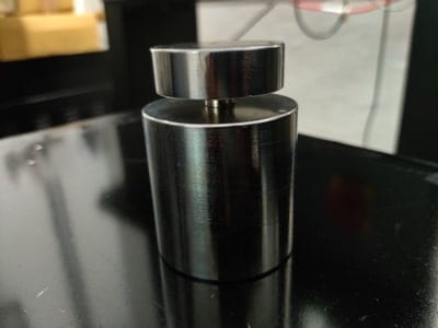
The measure of compressibility of the material is testing using the Volumetric compression test. A button specimen is used and a hydrostatic state of compression is applied on the specimen to evaluate it.
4) Uniaxial Compression Testing
Uniaxial compression refers to the compression of a button specimen of approx. 29mm diameter and 12.5 mm height. This test can be effectively utilized to replace the expensive biaxial extension test through proper control of the specimen and testing fixture surface friction and proper testing technique and methodology.
5) EquiBiaxial Tension Testing
Biaxial tensile testing is a highly accurate testing technique for mechanical characterization of soft materials. Typical materials tested in biaxial tension are soft and hard rubbers elastomers, polymeric thin films, and biological soft tissues.
The outputs from these tests are the stress vs strain curves in the principal deformation modes. Curve fitting is carried out on the experimental stress vs strain curves to generate the material constants.
These constants are obtained by comparing the stress- strain results obtained from the material model to the stress-strain data from experimental tests. Iterative procedure using least-squares fit method is used to obtain the constants, which reduces the relative error between the predicted and experimental values. The linear least squares fit method is used for material models that are linear in their coefficients e.g Neo-Hookean, Mooney-Rivlin, Yeoh etc. For material models that are nonlinear in the co-efficient relations e.g. Ogden etc, a nonlinear least squares method is used.
Are you looking for a plastic material testing laboratory near me, then look no further. We are a NABL ISO-17025 approved Plastics and Rubber Testing Laboratory based in Ahmedabad, India We provide the following testing services;
AdvanSES’ Plastic Testing Laboratory provides physical and mechanical testing of thermoplastics, polymers and composite materials to ensure these polymer materials meet quality control and application performance requirements
Physical and mechanical testing of polymers ensures that material complies with industry specifications and application requirements of aerospace, automotive, consumer goods, and biomedical industries. As a one-stop plastic testing laboratory for design development, quality control, performance assessment and failure analysis our vast physical and mechanical testing capabilities aincludes ASTM, ISO, IS, BS or DIN standards. Our ISO/IEC 17025:2017 accredited plastic testing laboratory services support design and development projects, Finite Element Analysis FEA, quality control, and problem-solving for all kinds of polymer materials and products.
Ash Content Test: This test is used in determining the amount of fillers in a specimen after the polymer has been burned off and is suitable for the determination of the ash content in rubber compounds. The test methods may be used for quality control. Test Method: ASTM D2584, D5630, ISO 3451
Compression Stress Relaxation Under Constant Deflection: This test is carried out under constant deflection in compression and helps in determining the ability of the material to maintain backforce under compressive stress. This test is used to determine the quality of material and their performance under constant compression application conditions. Test Method: ASTM D6147 B, ISO 3384
Compression Properties Test: This test helps in determining the behaviour of a material when it is subjected to a progressively increasing compressive load. The compressive strength of a material is the force per unit area that it can handle under compression deformation mode. AdvanSES has 3 load frames in its rubber testing laboratory to carry out these tests. Test Method: ASTM D695, ISO 604
Charpy Impact Test: This test helps in determining a thermoplastic or composite material’s resistance to resist impact. This test provides comparative values for various plastics easily and quickly. Test Method: ISO 179
Density And Specific Gravity Test: Our rubber testing laboratory carries out density and specific gravity tests on rubbers, TPEs, thermoplastics etc. This test helps in determining the mass per unit volume of material and the ratio of the mass of a given volume of material. Test Method: ASTM D792, ISO 1183
Flexural Properties Test: This test helps in determining the force required to bend a beam under 3 or 4 points load conditions. The flexural strength of a material is defined as its ability to resist deformation under such 3 point or 4 point loads. Test Method: ASTM D790, ISO 178
3 Point or 4 Point Bend Tests
FTIR (Fourier Transform Infrared Spectrometry) Test: This test helps in identification of polymers, thermoplastics, rubber materials. FTIR (Fourier Transform Infrared Spectroscopy) is an analytical tool for screening and identifying polymer samples. Test Method: ASTM E1252
Izod Impact Test: This test method similar to Charpy’s test method helps in determining a material’s resistance to an impact. The impactor is a swining pendulum. The result of the Izod test is reported in energy absobed per unit of specimen thickness. Test Method: ASTM D256, ISO 180
Tensile Test Of ThermoPlastics: This test helps in measuring the force required to break a specimen and the extent to which the specimen stretches or elongates to that breaking point. The ability of a material to resist breaking under tensile stress is one of the most important and widely used properties of materials used in structural applications. Test Method: ASTM D638, ISO 527
Axial Fatigue Testing of Polymer Thermplastic Materials
Axial Fatigue Test Of ThermoPlastics and Composites: This test helps in understanding the fatigue life of the material or part and assists in generating an S-N curve for the material. The ability of a material to resist breaking under constant cyclic tensile stress is one of the most important and widely used properties of materials used in structural applications. The data from these tests is used in understanding the endurance strength and crack initiation limits of the material. AdvanSES’ plastic testing laboratory can carry out these fatigue tests under stress or strain control and also at room and elevated temperatures. Test Method: ASTM D7791, ISO 13003
The heat deflection temperature of a reinforced or unreinforced polymer material is a measure of polymer’s resistance to distortion under an applied load at elevated temperatures.
Vicat softening temperature tests are used to identify the temperature at which a needle of specified dimensions penetrates into a plastic material specimen for a specified distance under applied loading conditions.
Compared with the Heat Deflection Temperature (HDT) Vicat softening temperature test measures the temperature at which the specimen loses its stiffness and softens. HDT test measures the temperature at which the specimen loses its load bearing capability. The Vicat point is closer to the actual melting or softening point of the polymer.
Test Methods: ASTM D648 and ISO 75; ASTM D1525 and ISO 306